
Counterbored Graphite Flange Bushings for Welding-Positioner Tilt Pivots
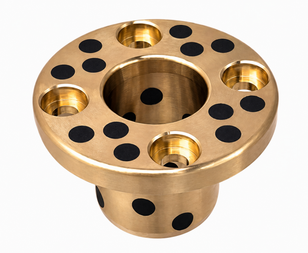
A welding positioner’s tilt bracket may oscillate on a shaft while a gearbox controls the workpiece angle. This page addresses a replaceable counterbored mounting-flange sleeve at that tilt joint, with separate attention to eccentric workpiece loads, fastener seating and the welding-current route.
Keep the bearing arrangement separate from the welding return path
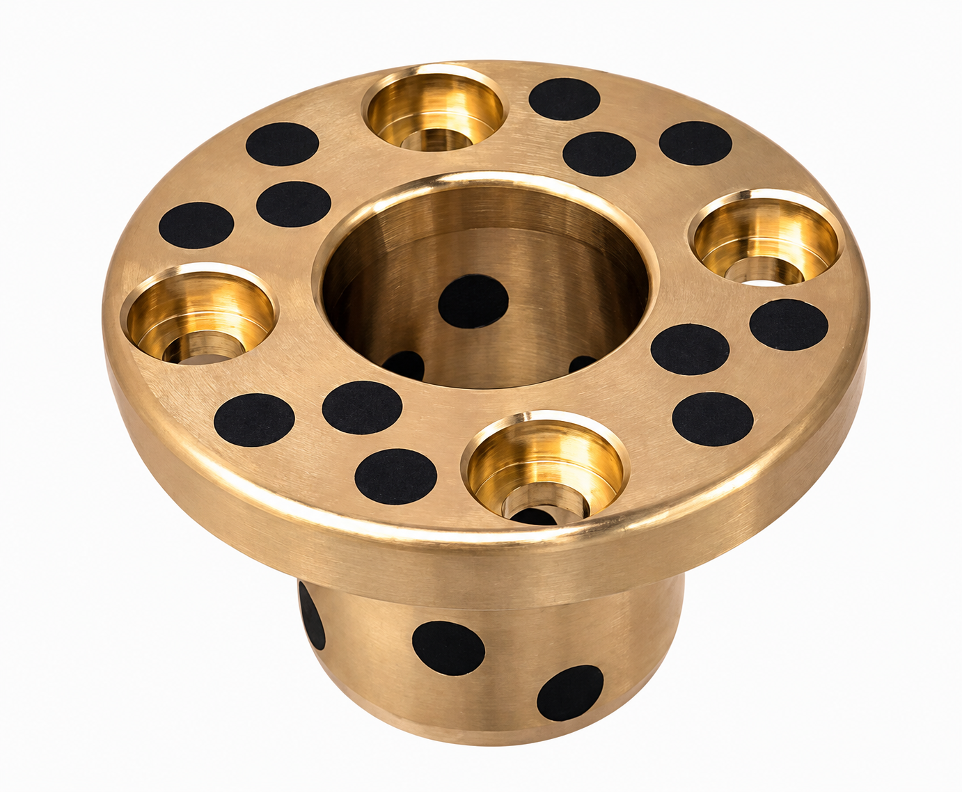
MPKZ/OFP03 has cylindrical counterbores for recessed fastener heads. Specify the bolt head diameter, counterbore depth, tool clearance and flange support thickness. Define where the radial load enters the sleeve and whether the graphite-plugged flange face carries an approved axial contact. Shaft retention and drive reaction must be shown on the assembly drawing.
Operating conditions and selection boundaries
Provide workpiece mass, maximum centre-of-gravity offset, tilt angle, braking torque and start/stop cycle. State the actual temperature at the bearing location and the shielding arrangement against spatter. The welding-current return path needs its own engineered provision; the sliding bearing is not being offered as a current collector.
This is an enquiry for a tilt-joint bearing component, not a certified positioner assembly, brake or electrical return device.
Specify the exact material standard, alloy or composite construction and any certificate requirements in the enquiry. Different national material designations are not treated as automatic equivalents. Availability and manufacturing details are confirmed in the quotation.
Dimensions and drawing information for quotation
| Drawing feature | Information to provide |
|---|---|
| Positioner loading | Workpiece mass, offset, orientation range and drive/brake reactions. |
| Counterbore geometry | Hole centres, head diameter, recess depth and tightening-tool access. |
| Bearing stack | Shaft shoulder, axial retention, support spacing and allowable play. |
| Thermal and electrical | Bearing temperature, spatter protection and separate current-return layout. |
Include quantity, units, drawing revision, inspection requirements and delivery destination. Distinguish measured wear from the intended new-part dimensions.
Installation and acceptance checks
Mount the flange against a flat, supported surface and verify that screw heads remain below the specified clearance plane. Check tilt motion with the approved assembly clearance. Keep debris and welding spatter out of the sliding interface and confirm the separate current-return arrangement before welding.
Confirm the lubrication and inspection plan for the specified material and duty. The application name does not establish a load rating, service-life guarantee or approval for the complete machine.
Frequently asked questions
Can welding current pass through this bearing?
Do not design it as the return conductor. Specify and review a separate current path.
Does the process temperature equal the bearing temperature?
No single temperature is assumed. Supply the measured or designed temperature at the installed bearing.
What load is needed for quotation?
Include eccentricity and operating orientation as well as workpiece mass; mass alone does not describe the joint reaction.
Request a drawing-based quotation
Send the assembly section, component drawing, quantity and operating conditions for welding positioner tilt pivot bushings. BONIU will review the geometry, material and installation requirements before confirming the quotation.