
MPSZ / OFP02 Graphite-Plugged Flanged Thrust Bushings with Countersunk Mounting Holes
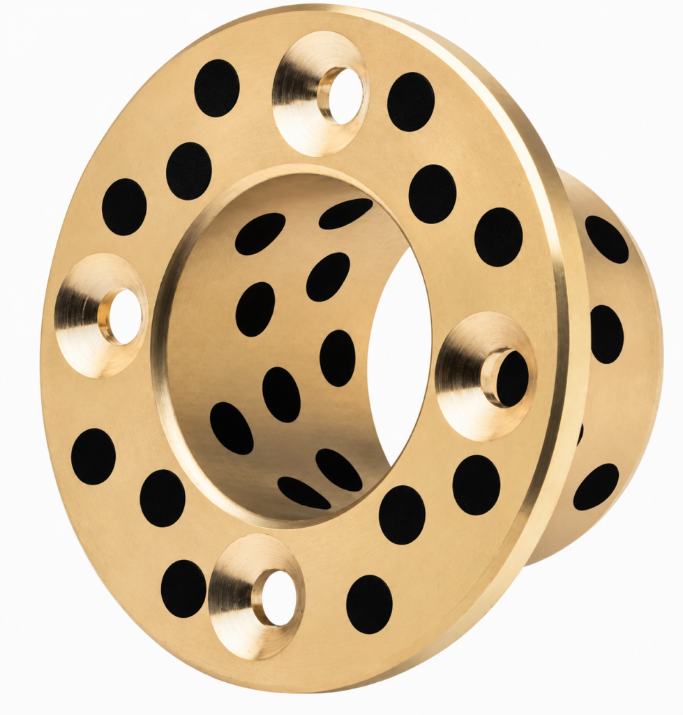
BONIU supplies MPSZ / OFP02 graphite-plugged copper-alloy flanged thrust bushings with countersunk mounting holes in the flange. The design combines a sleeve for radial guidance, a graphite-plugged flange face for the specified axial sliding duty, and mounting holes for securing the flange to the mating structure. Send your drawing and operating conditions to confirm the bearing and installation details.
MPSZ / OFP02 Flanged Thrust Bushings
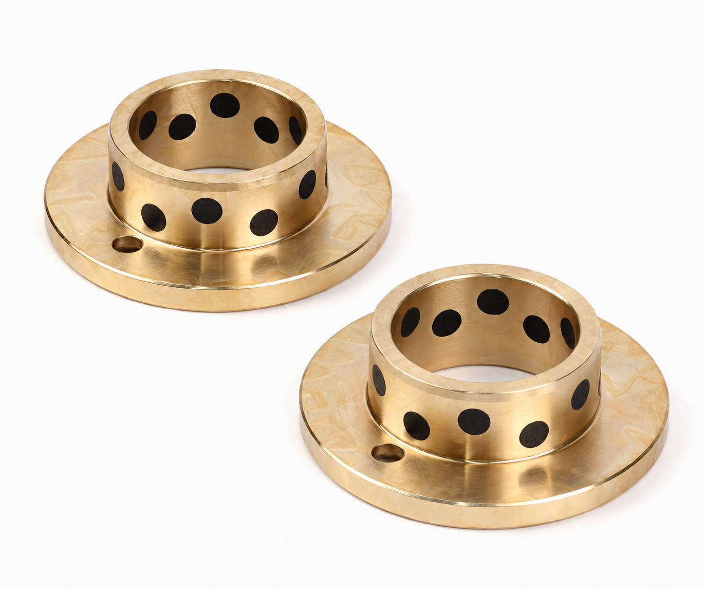
This bearing has graphite plugs on the cylindrical bearing surface and the flange face, together with conical screw-head recesses in the mounting holes. These are separate functional features: the sleeve guides the shaft or pin, the flange provides the intended axial sliding contact, and the fasteners retain the bearing in the assembly.
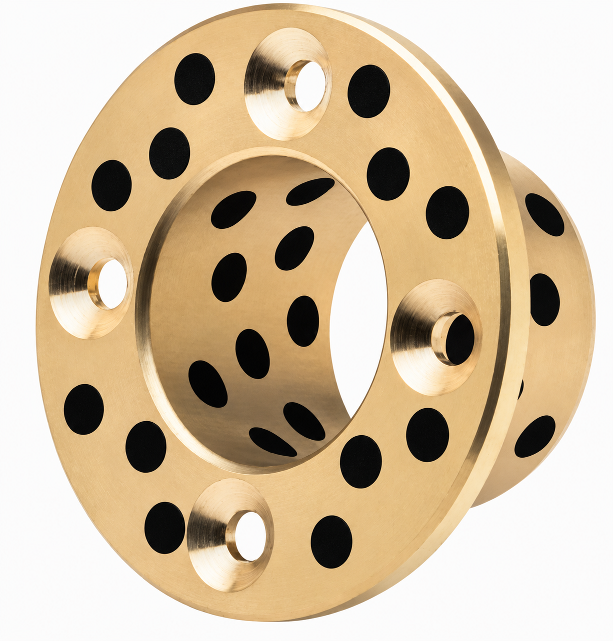
Enquiries may involve machinery pivots, guide assemblies, linkages and other bearing positions requiring radial support, axial contact and a flange fixing arrangement. Suitability depends on the complete load path, motion, counterfaces and installation. The mounting screws and flange bearing surface must each be checked for their assigned duty.
Countersunk Holes for Flange Mounting
The conical recesses receive a matching countersunk fastener head. Their geometry must be specified together with the screw and mating component. Confirm the included countersink angle, recess diameter or depth, through-hole diameter, hole quantity and pitch-circle diameter on the drawing. Do not select a screw solely from a photograph.
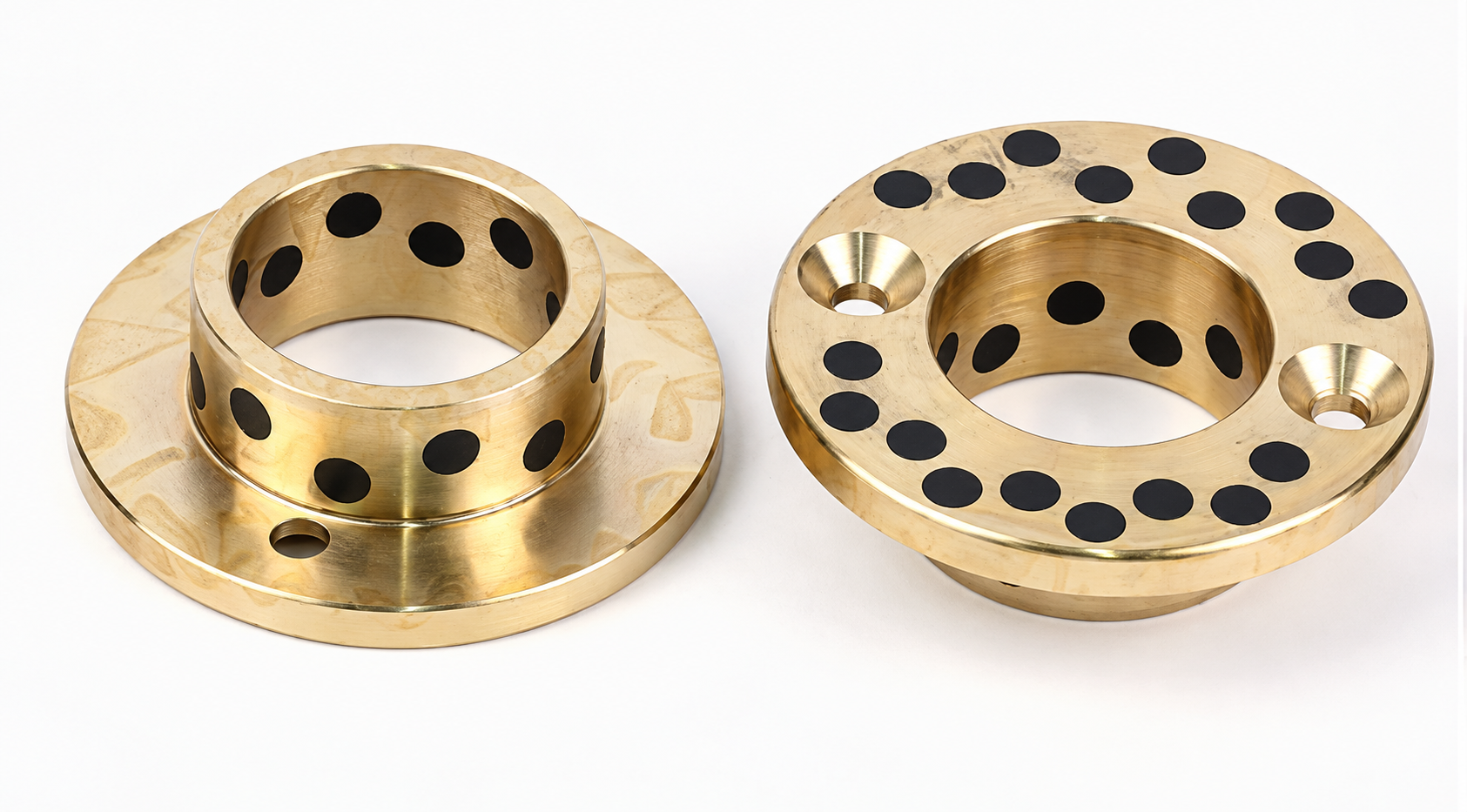
Where a mating part slides over the flange, confirm the required fastener-head position relative to the running face and provide suitable clearance. The screw head must not interfere with the moving component. Fastener torque, thread engagement and the strength of the supporting structure are assembly design requirements.
For the related thrust-flange product, see our MPGZ / OFP01 graphite-plugged flanged thrust bushings. Use the actual drawings to compare geometry and mounting arrangements; product designations alone do not establish interchangeability.
Graphite-Plugged Flange Thrust Face
The metal body supports the bearing load while the embedded graphite provides solid lubrication at the specified sliding surfaces. Graphite on the flange addresses a different contact surface from graphite in the bore. Identify the working thrust face and the required graphite pattern on the drawing.
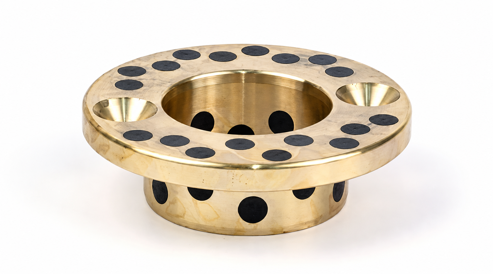
Confirm the copper alloy grade, graphite specification and operating conditions before ordering. A gold-coloured appearance does not establish an alloy grade, and a graphite-plugged flange does not imply an unlimited thrust capacity. Review radial and axial loads, sliding speed, duty cycle, temperature and the mating surface condition together.
Dimensions and Quotation Checklist
Send your drawing, quantity and application details. Dimensions, tolerances and inspection requirements are agreed for the actual order.
| Feature | Information to provide |
|---|---|
| Sleeve | Bore, outside diameter, overall length and length below the flange. |
| Flange | Outside diameter, thickness, transition radius, relief and working thrust face. |
| Mounting pattern | Number of holes, pitch-circle diameter, angular positions and orientation datum. |
| Countersunk holes | Through-hole diameter, countersink included angle, recess diameter or depth, and mating screw specification. |
| Material and graphite | Copper alloy grade, graphite specification and required plugged surfaces. |
| Assembly and operation | Shaft and housing fits, thrust counterface, radial and axial loads, motion, temperature and environment. |
| Order requirements | Quantity, drawing revision, inspection documents, packaging and destination. |
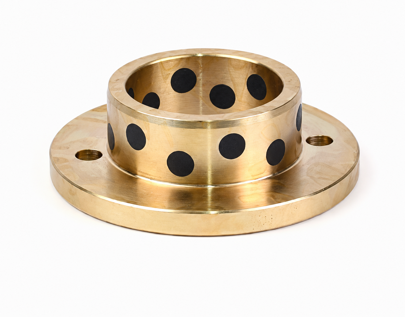
Installation and Fastener Clearance
Clean and deburr the housing, shaft, flange seat and mounting holes. Install the sleeve squarely using suitable tooling and support the metal body without striking the graphite plugs. Check the approved housing fit and shaft clearance before securing the flange.
Use fasteners with the correct head geometry and confirm their seating position. Follow the assembly drawing for tightening sequence and torque. Check that the flange is supported evenly, the bearing is not distorted, and no fastener projects into the moving part’s path. Verify both radial freedom and axial clearance after installation.
Confirm counterface finish, alignment and lubrication requirements for the actual bearing specification. Solid lubricant plugs do not remove the need to assess heat, contamination, corrosion and wear. Avoid machining the bore, flange face or countersinks without reviewing the effect on the bearing and its graphite pattern.
Frequently Asked Questions
What is the purpose of the conical holes in the flange?
They are countersunk mounting holes intended for matching fastener heads. Hole dimensions, included angle and screw-head clearance must be confirmed from the assembly drawing.
Does this design support radial and axial bearing duties?
The sleeve provides radial guidance and the graphite-plugged flange is intended for the specified axial sliding contact. The actual loads and operating conditions must be checked before selection.
Are the mounting holes the same as the graphite plug holes?
No. The open countersunk holes are for fasteners; the filled graphite locations provide solid lubrication on the specified bearing surfaces.
Can MPSZ / OFP02 replace another supplier’s flanged bearing?
Send both drawings and the operating requirements for review. Compare the alloy, graphite arrangement, dimensions, fits and mounting details before confirming interchangeability.
Can you quote a custom mounting pattern?
Send the hole quantity, pitch-circle diameter, countersink geometry, orientation and complete bearing dimensions. BONIU will review the drawing and confirm the quotation and inspection requirements.
Request an MPSZ / OFP02 Quote
Send your drawing, quantity, mounting screw details and radial and axial operating conditions. BONIU will confirm the bearing construction and countersunk flange arrangement for your order.
Countersunk fixing holes for a clear sliding face
This version addresses an assembly where conical screw heads must sit below a nearby moving member or thrust counterface. Specify the actual screw standard; a countersunk recess must match its head geometry. A flush appearance in a photograph does not establish clearance under load.
| Drawing review | Information for quotation |
|---|---|
| Conical seat | State included angle, major diameter, depth and the specified screw head dimensions. |
| Hole coordinates | Dimension the hole pattern from the bore axis or agreed datums, including angular orientation. |
| Moving envelope | Show the minimum gap above the tightened screw heads and the swept area of the mating part. |
Installation and operating boundaries
Confirm screw seating and the remaining flange section around each hole before approving the drawing. Tighten using the assembly designer’s specified method; an arbitrary torque can distort a flange or damage a seat. Recheck seating and sliding clearance after fastening. Use a counterbored design where the drawing requires a cylindrical screw-head recess instead.
Include the drawing revision, quantity, required delivery destination and inspection-document requirements. Photographs show geometry; they do not establish an alloy grade, coating test result or service rating. BONIU reviews the requested specification before confirming the quotation.
Purchasing questions
Is a countersunk hole the same as a counterbore?
No. This page owns the conical-seat procurement intent. A counterbore has a cylindrical recess and a flat seating shoulder.
Can the screws locate the bearing accurately?
Do not assume clearance fixing holes provide precision location. Show the intended pilot, fitted diameter or other locating feature on the drawing.
Can the moving member pass directly over the fixing holes?
Provide the motion envelope and required contact track so interrupted support, screw clearance and flange contact can be reviewed.
Related selection routes
MPKZ / OFP03 Graphite-Plugged Flanged Thrust Bushings with Counterbored Mounting Holes; bearing materials; automation guidance applications; Bearing selection and installation guides.
Request a drawing-based quotation
Send the interface drawing and operating details through our enquiry page. Identify the required material by its exact standard and grade; proposed alternatives require approval.