
Round Mounting-Flange Graphite-Plugged Bushings
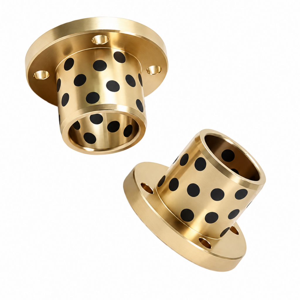
Graphite-plugged copper-alloy bushings with a round mounting flange and fixing holes. Review the bolt pattern, locating fit and solid-lubricant working surfaces against your drawing.
Graphite-plugged sleeve with a round mounting flange
BONIU round mounting-flange graphite-plugged bushings combine a solid copper-alloy sleeve with an integral circular flange and fixing holes. Embedded graphite plugs form part of the solid-lubricant system on the specified bearing surfaces. The flange provides a bolted mounting interface to the surrounding structure.
These parts may also be described as round-flange bronze graphite bushings or bolt-mounted solid-lubricant sleeve bearings. Specify the exact alloy and lubricant requirements; the photograph shows the general form rather than a fixed size, material grade or operating rating.
Fixing holes, locating fits and alignment
Define how the sleeve is located before selecting the fixing arrangement. Confirm whether its outside diameter fits into a housing bore or passes through a clearance opening. Show the flange seating face and the relationship between the shaft axis, housing and fixing holes.
Specify hole count, pitch-circle diameter, angular spacing and orientation. Where recesses or special fasteners are required, include their exact geometry. Fixing holes are attachment features; they are not lubricant ports unless expressly designed for that purpose.
The bolts should secure an evenly seated flange without pulling a misaligned sleeve into position. Flange support, fastener selection and tightening requirements are reviewed as part of the assembly.
Identify the working surface and lubricant system
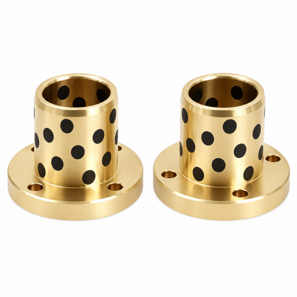
Review the alloy, embedded lubricant, mating shaft and duty together. Provide load, rotation speed or oscillation, stroke where applicable, cycle frequency, temperature and exposure to dust, water or chemicals.
The images show graphite plugs in the sleeve region. A smooth flange face should not be assumed to have the same lubrication arrangement as the bore. If that face carries axial sliding load, specify its contact area, counterface, lubrication and running clearance separately.
Self-lubricating does not mean inspection-free or suitable for every dry-running condition. Confirm commissioning lubrication, any supplementary lubricant and the maintenance plan for the selected material system.
For alloy references, see the copper-alloy composition guide. Material colour and plug appearance do not establish composition or load capacity.
Drawing and quotation checklist
| Design area | Details to provide |
|---|---|
| Sleeve | Bore, outside diameter, body length, overall length, units and tolerances |
| Round flange | Diameter, thickness, seating face, shoulder radius and edge details |
| Mounting holes | Count, diameter, bolt circle, spacing, orientation and any recess dimensions |
| Installed fit | Shaft and housing dimensions, locating method, running clearance and alignment requirements |
| Material pair | Alloy grade and standard, solid lubricant, shaft material, hardness and finish |
| Duty and supply | Load, motion, speed, environment, quantity, drawing revision and inspection requirements |
Mark whether length includes the flange. For a replacement, compare the complete mounting envelope and working surfaces, not just the bore and bolt pattern.
Installation and commissioning
- Clean and inspect the bushing, housing bore, flange seat and shaft. Remove debris and burrs without altering the bearing surface or graphite plugs.
- Confirm the specified locating fit and insertion direction. If press fitting is required, use controlled pressure and an aligned mandrel rather than hammering.
- Seat the flange evenly and align the fixing pattern without forcing the sleeve. Tighten the specified fasteners to the assembly requirements.
- Check the installed bore, shaft alignment and free movement. Verify radial and axial clearances wherever they are required.
- Follow the agreed commissioning lubrication instructions and monitor noise, temperature and wear before applying full duty.
The installed bore may differ from the free-state measurement. Use the drawing and assembly procedure to establish acceptance criteria rather than a generic fit selected from the photograph.
Compare related flange designs
| Form | Selection focus |
|---|---|
| Round mounting-flange graphite bushing | Bolted circular interface, locating fit and embedded-lubricant working surfaces |
| Square mounting-flange graphite bushing | Rectangular envelope, fixing-hole coordinates and installation space |
| Round mounting-flange plain bushing | Smooth solid-metal sleeve with a separately specified lubrication plan |
Explore square-flange graphite bushings, round mounting-flange plain bushings and the mounting flange range. For separate axial support, review graphite-plugged thrust washers.
Potential applications include guide assemblies, tooling and pivots with a suitable round bolted mounting interface. Confirm actual motion, shock loads, contamination and structural alignment during selection.
Frequently asked questions
Are the fixing holes oil holes?
The illustrated flange holes are mounting features. Any lubricant supply hole must be identified separately on the drawing.
Does the flange automatically support thrust?
No. Review flange strength and the axial load path. Sliding contact on the face also requires a defined lubricant system, counterface and clearance.
Can the bolt circle or body length be changed?
Send the complete drawing and quantity. Geometry, material and manufacturing feasibility are reviewed before quotation.
Can a plain flange bushing be replaced directly?
Compare fits, alloy, lubrication, shaft compatibility and service conditions. Matching dimensions alone is insufficient.
Is additional grease always needed?
No universal rule applies. Confirm commissioning and service lubrication for the actual alloy, graphite formulation and operating duty.
Request a drawing review
Send your drawing revision, quantity, alloy and operating conditions to sales@boniubushing.com or use the contact page. Include the mounting arrangement and mating-shaft details.
Final material, tolerances, lubricant arrangement, availability and delivery are confirmed during quotation.
General installation reference: OILES plain-bearing installation guidance. Product-specific fits and ratings in that reference do not define BONIU specifications.