
Round Mounting-Flange Plain Bronze Bushings
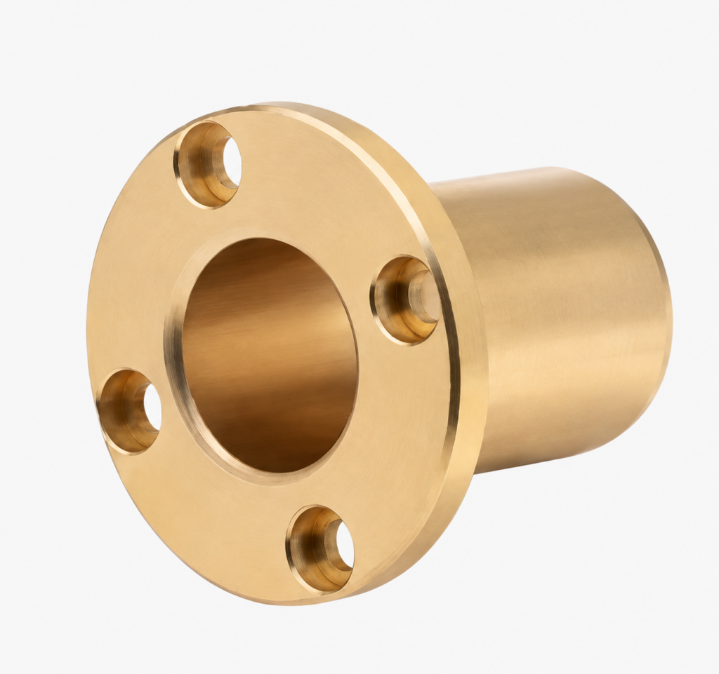
Plain bronze and brass sleeve bushings with a round bolted mounting flange. Specify the bore, fixing pattern, installed fit and lubrication for drawing review.
Round flange with mounting holes
BONIU round mounting-flange plain bushings combine a solid copper-alloy sleeve with a circular flange and fixing holes. The sleeve provides a sliding interface around the shaft, while the flange offers a bolted attachment to the supporting structure. The illustrated form has four recessed fixing holes and a smooth bore without graphite plugs.
Specify the part as a round-flange bronze or brass sleeve bushing with mounting holes, together with the exact alloy. The photograph identifies the form; it does not define a material grade, standard size or capacity.
Define the bolted mounting interface
Start with the housing and shaft arrangement. Confirm whether the sleeve outside diameter locates in a precision housing bore or passes through a clearance opening. Agree the locating features, flange seating surface and bolt arrangement so the assembly can maintain alignment without distorting the sleeve.
The fixing holes secure the flange, but hole count alone does not establish compatibility with an existing component. Define the pitch-circle diameter, angular spacing and hole orientation relative to any oil hole or other feature. Specify whether the fastener recess is a counterbore, countersink or another profile, including its dimensions.
Bolts should not be used to pull a misaligned sleeve into position. Flange support, fastener choice and tightening requirements belong to the assembly design. If the flange face carries an axial sliding load, review that contact separately; a mounting flange is not automatically a thrust bearing.
Drawing and quotation checklist
| Feature | Information to specify |
|---|---|
| Sleeve | Bore, outside diameter, body length, overall length and units |
| Round flange | Outside diameter, thickness, seating face and shoulder transition |
| Fixing pattern | Hole count, pitch-circle diameter, angular spacing and orientation |
| Hole details | Through-hole diameter, recess type, diameter, depth or angle, and edge distances |
| Fits and geometry | Shaft and housing sizes, installed running clearance, bore position and flange-face tolerances |
| Lubrication | Oil or grease supply, oil holes and groove geometry where required |
| Material and order | Alloy grade, standard, quantity, drawing revision and inspection requirements |
Show both body length and overall length to clarify whether the flange is included. For a replacement, compare the full mounting envelope and shaft location rather than bore size alone.
Material, lubrication and service conditions
Select the bronze or brass grade together with the mating shaft and lubrication plan. Provide radial and axial loads, rotation or oscillation, speed or stroke, duty cycle, temperature and exposure to water, chemicals or abrasive dust.
Material options are reviewed against your drawing. State the required tin bronze, high-tensile brass or other specified copper alloy and its standard. Surface colour is not a reliable material identification method. Use the copper-alloy composition guide for reference, then confirm the actual grade.
This smooth solid-metal construction is not automatically self-lubricating. Agree the lubricant, supply route and maintenance plan. A graphite-plugged or composite bearing cannot be replaced solely by matching the dimensions.
Installation and commissioning
- Clean and inspect the housing bore, flange seat, fixing holes and shaft. Check edge relief and clearance around the sleeve-to-flange transition.
- Confirm the specified locating fit. If press fitting is required, use aligned tooling and controlled pressure; avoid hammering or loading unsupported flange edges.
- Seat the flange evenly. Align the fixing pattern without forcing the sleeve, and tighten the selected fasteners to the assembly requirements.
- Verify the installed bore, shaft alignment and free movement. Check running clearance and that fasteners do not interfere with moving components.
- Connect the lubricant supply where specified, apply the commissioning lubricant and inspect noise, temperature and wear during initial operation.
Installed fits and bolt tightening requirements depend on the actual geometry, materials and load path. They should not be inferred from the image.
Frequently asked questions
Are four holes supplied on every size?
The image shows four holes. Hole count, spacing and recess geometry are confirmed from the approved drawing for each part.
Do the bolts replace a housing locating fit?
Not automatically. The assembly must define how the sleeve is located and supported and how loads pass into the structure.
Can the flange carry axial load?
Review flange strength and the load path. If there is sliding contact on the face, also specify its lubrication, counterface and running clearance.
Can this run without grease or oil?
Do not assume dry-running suitability for a smooth solid-metal sleeve. Confirm the material pair and lubrication requirements for the actual duty.
Can a different bolt circle or sleeve length be reviewed?
Send the complete drawing with quantity and service conditions. Geometry, material and manufacturing feasibility are reviewed before quotation.
Request a drawing review
Send the drawing revision, alloy, quantity and operating conditions to sales@boniubushing.com or use the contact page. Include the housing arrangement, fixing pattern and lubrication plan.
Final material, feature tolerances, inspection scope, availability and delivery are confirmed during quotation.
General references: Copper Development Association material-selection guide and OILES plain-bearing installation guidance. Product-specific fits and ratings in those references do not define BONIU specifications.