
Flanged Graphite-Plugged Copper-Alloy Bushings
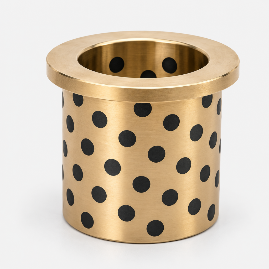
Copper-alloy sleeve bushings with embedded graphite and an integral round locating flange. Specify the flange seat, installed fit and working surfaces for your assembly.
Graphite-plugged sleeve with an integral locating flange
BONIU flanged graphite-plugged bushings combine a copper-alloy sleeve with an integral round flange. Embedded graphite plugs form part of the bearing’s solid-lubricant system. The flange provides a shoulder for axial positioning within a suitable housing arrangement.
This page covers the locating-flange form shown in the photographs. Unlike a bolted mounting flange, this design has no flange fixing holes. Define the housing fit, flange seat and retention method as part of the assembly drawing. The term “flanged” describes the shape; it does not establish a particular manufacturing process or material grade.
Dimensions and mating parts to specify
| Feature | Required information |
|---|---|
| Sleeve | Bore diameter, outside diameter, sleeve length and tolerances |
| Flange | Outside diameter, thickness, seating face and overall length |
| Shoulder transition | Fillet radius, housing chamfer or relief and edge breaks |
| Installed assembly | Housing size, shaft size, locating fit, retention and running clearance |
| Bearing system | Alloy grade and standard, graphite formulation, plug layout and sliding surfaces |
| Service conditions | Load direction, peak load, motion, speed, temperature and contamination |
State whether the quoted length includes the flange. Include units and drawing revision. For a replacement part, provide the mating shaft and housing information rather than relying on the loose bushing dimensions alone.
Working surfaces and lubrication
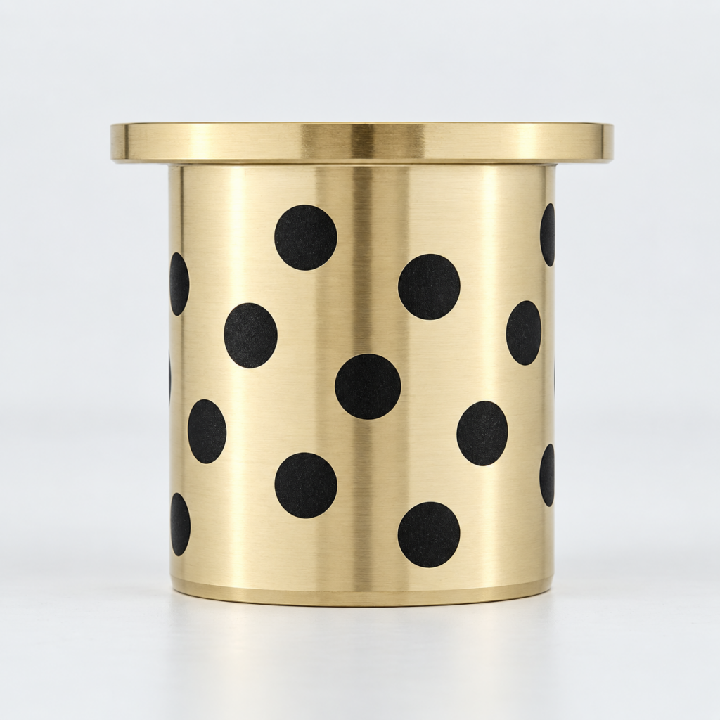
Identify the bore as a sliding interface and state whether the outside diameter remains fixed in the housing. The photograph shows graphite plugs in the sleeve region and a smooth flange face. It does not establish a graphite-lubricated thrust face.
If the flange contacts a moving mating surface, review axial load, contact area, counterface, lubrication and clearance separately. Where the flange only locates the bushing against a stationary seat, describe that condition on the assembly drawing.
Dry-running suitability, initial lubrication and any supplementary lubricant are confirmed for the selected alloy, graphite system and service conditions. A self-lubricating designation does not remove the need for inspection.
Confirm the material by grade and standard. Brass, bronze and other copper alloys cannot be identified reliably from the colour of a product image. Consult the copper-alloy composition guide when preparing the material specification.
Installation and first operation
- Inspect the sleeve, graphite plugs, shaft, housing and flange seat. Clean away burrs and debris without modifying the working surfaces.
- Check that the shoulder radius clears the housing entrance and that the flange can seat squarely. Confirm the intended assembly direction and axial retention.
- Use the specified locating fit and suitable aligned tooling. Where pressing is required, apply controlled force through the approved tooling contact area; avoid hammering or loading an unsupported flange edge.
- Measure the installed bore and confirm shaft alignment and running clearance. Do not assume the loose-part bore remains unchanged after installation.
- Follow the agreed commissioning lubrication plan. Check free movement and monitor temperature, noise and wear during initial operation.
The drawing and assembly specification determine acceptance limits. This page does not assign a universal interference fit, shaft tolerance or installation force.
Compare flange and sleeve designs
Consider this form for pivot, guide and tooling assemblies that need a sleeve bearing with a locating shoulder. Review actual load and motion before confirming suitability, including reversing movement, shock loading and maintenance access.
| Product form | Selection focus |
|---|---|
| Flanged graphite-plugged bushing | Locating shoulder, housing retention and graphite-bearing surfaces |
| Straight graphite-plugged sleeve | Cylindrical installation with a separately designed axial location |
| Plain flanged copper-alloy bushing | Integral flange with a separately specified lubrication arrangement |
| Mounting-flange graphite bushing | Fixing holes, bolted interface and flange support |
Compare straight graphite-plugged bushings, plain flanged bushings and round mounting-flange graphite bushings. For a separate axial sliding element, review graphite-plugged thrust washers.
Frequently asked questions
Does this flange have mounting holes?
The illustrated locating flange has no fixing holes. For a bolted design, use a mounting-flange product and specify its fixing pattern.
Can the flange carry axial load?
Confirm the axial load path and flange strength. Any sliding contact on the flange also requires a specified bearing surface, lubricant and counterface.
Is the product made by bending the sleeve edge?
No manufacturing process is declared by the photographs or the name. Confirm the required construction and material during drawing review.
Can I use it without adding grease?
Confirm dry-running suitability and commissioning lubrication for the actual graphite formulation, alloy and operating duty.
Can dimensions and graphite layout be customised?
Send the drawing and operating conditions for a feasibility review. Final dimensions, material, lubricant arrangement and supply details are agreed during quotation.
Request a drawing review
Send your drawing revision, required quantity and operating conditions to sales@boniubushing.com or use the contact page. Include the bore, outside diameter, sleeve length, flange dimensions, alloy and mating-part details.
Material, graphite arrangement, tolerances, inspection requirements, availability and delivery are confirmed before supply.